
Forces Due To Pipe Bends
The momentum change and the unbalanced internal pressure of the water leads to forces on the pipes The force diagram in figure is a convenient method for finding the resultant force on a bend. The forces can be resolved into X and Y components to find the magnitude and direction of the resultant force on the pipe.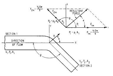
V1= velocity before change in size of pipe, ft /s (m/s)
V2= velocity after change in size of pipe, ft /s (m/s)
p1= pressure before bend or size change in pipe, lb/ft2
(kPa)
p2= pressure after bend or size change in pipe, lb/ft2
(kPa)
A1= area before size change in pipe, ft2 (m2)
A2= area after size change in pipe, ft2 (m2)
F2m= force due to momentum of water in section 2 V2Qw/g
F1m= force due to momentum of water in section 1 V1Qw/g
P2= pressure of water in section 2 times area of section 2 p1 A1
P1= pressure of water in section 1 times area of section 1 p1 A1
w= unit weight of liquid, lb/ft3 (kg/m3)
Q= discharge, ft3/s (m3/s)
If the pressure loss in the bend is neglected and there is no change in magnitude of velocity around the bend,then
R=2A[(wV2/g)+p]cosine of angle between pipes
where R resultant force on bend, lb (N)
p= pressure, lb/ft2 (kPa)
w= unit weight of water, 62.4 lb/ft3 (998.4 kg/m3)
V= velocity of flow, ft/s (m/s)
g= acceleration due to gravity, 32.2 ft/s2 (9.81 m/s2)
A= area of pipe, ft2 (m2)
No comments:
Post a Comment