
Project Report - Six Months Summer Training
Here is the project report of a civil engineering student who has spent 6 months on a training site.Due to security reasons,the project details, estimation, some portion of design and quantity calculations have been omitted.But to help the civil engineering students we had shown all the necessary works..
Sequence of Structure Work
1) Site Clearance
2) Demarcation of Site
3) Positioning of Central coordinate ie (0,0,0) as per grid plan
4) Surveying and layout
5) Excavation
6) Laying of PCC
7) Bar Binding and placement of foundation steel
8 ) Shuttering and Scaffolding
9) Concreting
10) Electrical and Plumbing
11) Deshuttering
12) Brickwork
13) Doors and windows frames along with lintels
14) Wiring for electrical purposes
15) Plastering
16) Flooring and tiling work
17) Painting
18) Final Completion and handing over the project
Construction Process And Materials Used
Site Clearance- The very first step is site clearance which involves removal of grass and vegetation along with any other objections which might be there in the site location.
Demarcation of Site- The whole area on which construction is to be done is marked so as to identify the construction zone. In our project, a plot of 450*350 sq ft was chosen and the respective marking was done.
Positioning of Central coordinate and layout- The centre point was marked with the help of a thread and plumb bob as per the grid drawing. With respect to this center point, all the other points of columns were to be decided so its exact position is very critical.
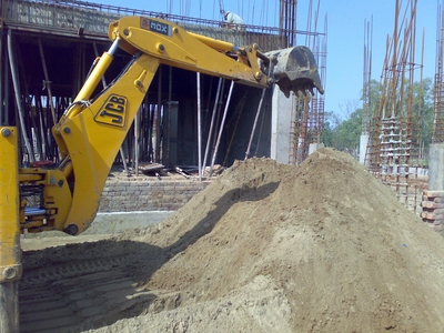
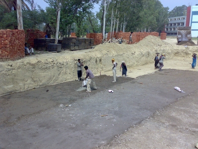
Excavation
Excavation was carried out both manually as well as mechanically. Normally 1-2 earth excavators (JCB’s) were used for excavating the soil. Adequate precautions are taken to see that the excavation operations do not damage the adjoining structures. Excavation is carried out providing adequate side slopes and dressing of excavation bottom. The soil present beneath the surface was too clayey so it was dumped and was not used for back filling. The filling is done in layer not exceeding 20 cm layer and than its compacted. Depth of excavation was 5’4” from Ground Level.
PCC – Plain Cement Concrete
After the process of excavation, laying of plain cement concrete that is PCC is done. A layer of 4 inches was made in such a manner that it was not mixed with the soil. It provides a solid bas for the raft foundation and a mix of 1:5:10 that is, 1 part of cement to 5 parts of fine aggregates and 10 parts of coarse aggregates by volume were used in it. Plain concrete is vibrated to achieve full compaction. Concrete placed below ground should be protected from falling earth during and after placing. Concrete placed in ground containing deleterious substances should be kept free from contact with such a ground and with water draining there from during placing and for a period of seven days. When joint in a layer of concrete are unavoidable, and end is sloped at an angle of 30 and junctions of different layers break joint in laying upper layer of concrete. The lower surface is made rough and clean watered before upper layer is laid.
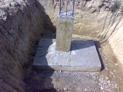
Laying of Foundation
At our site, Raft foundations are used to spread the load from a structure over a large area, normally the entire area of the structure. Normally raft foundation is used when large load is to be distributed and it is not possible to provide individual footings due to space constraints that is they would overlap on each other. Raft foundations have the advantage of reducing differential settlements as the concrete slab resists differential movements between loading positions. They are often needed on soft or loose soils with low bearing capacity as they can spread the loads over a larger area.
In laying of raft foundation, special care is taken in the reinforcement and construction of plinth beams and columns. It is the main portion on which ultimately whole of the structure load is to come. So a slightest error can cause huge problems and therefore all this is checked and passed by the engineer in charge of the site.
Apart from raft foundation, individual footings were used in the mess area which was extended beyond the C and D blocks.
Cement
Portland cement is composed of calcium silicates and aluminate and aluminoferrite It is obtained by blending predetermined proportions limestone clay and other minerals in small quantities which is pulverized and heated at high temperature – around 1500 deg centigrade to produce ‘clinker’. The clinker is then ground with small quantities of gypsum to produce a fine powder called Ordinary Portland Cement (OPC). When mixed with water, sand and stone, it combines slowly with the water to form a hard mass called concrete. Cement is a hygroscopic material meaning that it absorbs moisture In presence of moisture it undergoes chemical reaction termed as hydration. Therefore cement remains in good condition as long as it does not come in contact with moisture. If cement is more than three months old then it should be tested for its strength before being taken into use.
The Bureau of Indian Standards (BIS) has classified OPC in three different grades The classification is mainly based on the compressive strength of cement-sand mortar cubes of face area 50 cm2 composed of 1 part of cement to 3 parts of standard sand by weight with a water-cement ratio arrived at by a specified procedure. The grades are
(i) 33 grade
(ii) 43 grade
(iii) 53 grade
The grade number indicates the minimum compressive strength of cement sand mortar in N/mm2 at 28 days, as tested by above mentioned procedure.
Portland Pozzolana Cement (PPC) is obtained by either intergrinding a pozzolanic material with clinker and gypsum, or by blending ground pozzolana with Portland cement. Nowadays good quality fly ash is available from Thermal Power Plants, which are processed and used in manufacturing of PPC.
Advantages of using Portland pozzolana cement over OPC
Pozzolana combines with lime and alkali in cement when water is added and forms compounds which contribute to strength, impermeability and sulphate resistance. It also contributes to workability, reduced bleeding and controls destructive expansion from alkali-aggregate reaction. It reduces heat of hydration thereby controlling temperature differentials, which causes thermal strain and resultant cracking n mass concrete structures like dams. The colour of PPC comes from the colour of the pozzolanic material used. PPC containing fly ash as a pozzolana will invariably be slightly different colour than the OPC.One thing should be kept in mind that is the quality of cement depends upon the raw materials used and the quality control measures adopted during its manufacture, and not on the shade of the cement. The cement gets its colour from the nature and colour of raw materials used, which will be different from factory to factory, and may even differ in the different batches of cement produced in a factory. Further, the colour of the finished concrete is affected also by the colour of the aggregates, and to a lesser extent by the colour of the cement. Preference for any cement on the basis of colour alone is technically misplaced.
Settling Of Cement
When water is mixed with cement, the paste so formed remains pliable and plastic for a short time. During this period it is possible to disturb the paste and remit it without any deleterious effects. As the reaction between water and cement continues, the paste loses its plasticity. This early period in the hardening of cement is referred to as ‘setting’ of cement.
Initial and final setting time of cement
Initial set is when the cement paste loses its plasticity and stiffens considerably. Final set is the point when the paste hardens and can sustain some minor load. Both are arbitrary points and these are determined by Vicat needle penetration resistance
Slow or fast setting normally depends on the nature of cement. It could also be due to extraneous factors not related to the cement. The ambient conditions play an important role. In hot weather, the setting is faster, in cold weather, setting is delayed Some types of salts, chemicals, clay, etc if inadvertently get mixed with the sand, aggregate and water could accelerate or delay the setting of concrete.
Storage of Cement
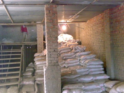
It needs extra care or else can lead to loss not only in terms of financial loss but also in terms of loss in the quality. Following are the don’t that should be followed -
(i) Do not store bags in a building or a godown in which the walls, roof and floor are not completely weatherproof.
(ii) Do not store bags in a new warehouse until the interior has thoroughly dried out.
(iii) Do not be content with badly fitting windows and doors, make sure they fit properly and ensure that they are kept shut.
(iv) Do not stack bags against the wall. Similarly, don’t pile them on the floor unless it is a dry concrete floor. If not, bags should be stacked on wooden planks or sleepers.
(v) Do not forget to pile the bags close together
(vi) Do not pile more than 15 bags high and arrange the bags in a header-and-stretcher fashion.
(vii) Do not disturb the stored cement until it is to be taken out for use.
(viii) Do not take out bags from one tier only. Step back two or three tiers.
(ix) Do not keep dead storage. The principle of first-in first-out should be followed in removing bags.
(x) Do not stack bags on the ground for temporary storage at work site. Pile them on a raised, dry platform and cover with tarpaulin or polythene sheet.
Coarse Aggregate
Coarse aggregate for the works should be river gravel or crushed stone .It should be hard, strong, dense, durable, clean, and free from clay or loamy admixtures or quarry refuse or vegetable matter. The pieces of aggregates should be cubical, or rounded shaped and should have granular or crystalline or smooth (but not glossy) non-powdery surfaces.Aggregates should be properly screened and if necessary washed clean before use.
Coarse aggregates containing flat, elongated or flaky pieces or mica should be rejected. The grading of coarse aggregates should be as per specifications of IS-383.
After 24-hrs immersion in water, a previously dried sample of the coarse aggregate should not gain in weight more than 5%.
Aggregates should be stored in such a way as to prevent segregation of sizes and avoid contamination with fines.
Depending upon the coarse aggregate color, there quality can be determined as:
Black => very good quality
Blue => good
Whitish =>bad quality
Fine Aggregate
Aggregate which is passed through 4.75 IS Sieve is termed as fine aggregate. Fine aggregate is added to concrete to assist workability and to bring uniformity in mixture. Usually, the natural river sand is used as fine aggregate. Important thing to be considered is that fine aggregates should be free from coagulated lumps.
Grading of natural sand or crushed stone i.e. fine aggregates shall be such that not more than 5 percent shall exceed 5 mm in size, not more than 10% shall IS sieve No. 150 not less than 45% or more than 85% shall pass IS sieve No. 1.18 mm and not less than 25% or more than 60% shall pass IS sieve No. 600 micron.
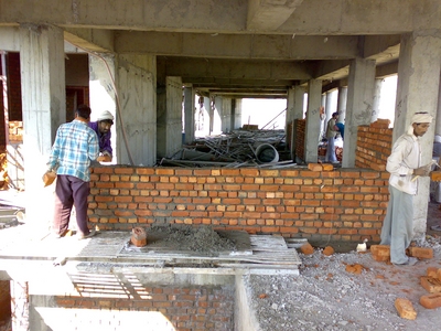
BRICKWORK
Brickwork is masonry done with bricks and mortar and is generally used to build partition walls. In our site, all the external walls were of concrete and most of the internal walls were made of bricks. English bond was used and a ration of 1:4 (1 cement: 4 coarse sand) and 1:6 were used depending upon whether the wall is 4.5 inches or 9 inches. The reinforcement shall be 2 nos. M.S. round bars or as indicated. The diameter of bars was 8mm. The first layer of reinforcement was used at second course and then at every fourth course of brick work. The bars were properly anchored at their ends where the portions and or where these walls join with other walls. The in laid steel reinforcement was completely embedded in mortar.
Bricks can be of two types. These are:
1) Traditional Bricks-The dimension if traditional bricks vary from 21 cm to 25cm in length,10 to 13 cm in width and 7.5 cm in height in different parts of country .The commonly adopted normal size of traditional brick is 23 * 11.5*7.5 cm with a view to achieve uniformity in size of bricks all over country.
2) Modular Bricks- Indian standard institution has established a standard size of bricks such a brick is known as a modular brick. The normal size of brick is taken as 20*10*10 cm whereas its actual dimensions are 19*9*9 cm masonry with modular bricks workout to be cheaper there is saving in the consumption of bricks, mortar and labour as compared with masonry with traditional bricks.
Strength of brick masonry
The permissible compressive stress in brick masonry depends upon the following factors:
1. Type and strength of brick.
2. Mix of motor.
3. Size and shape of masonry construction.
The strength of brick masonry depends upon the strength of bricks used in the masonry construction. The strength of bricks depends upon the nature of soil used for making and the method adopted for molding and burning of bricks .since the nature of soil varies from region to region ,the average strength of bricks varies from as low as 30kg/sq cm to 150 kg /sq cm the basic compressive stress are different crushing strength.
There are many checks that can be applied to see the quality of bricks used on the site.Normally the bricks are tested for Compressive strength, water absorption, dimensional tolerances and efflorescence. However at small construction sites the quality of bricks can be assessed based on following, which is prevalent in many sites.
• Visual check - Bricks should be well burnt and of uniform size and color.
• Striking of two bricks together should produce a metallic ringing sound.
• It should have surface so hard that can’t be scratched by the fingernails.
• A good brick should not break if dropped in standing position from one metre above ground level.
• A good brick shouldn’t absorb moisture of more than 15-20% by weight, when soaked in water For example; a good brick of 2 kg shouldn’t weigh more than 2.3 to 2.4 kg if immersed in water for 24 hours.
Precautions to be taken in brick masonry work
• Bricks should be soaked in water for adequate period so that the water penetrates
to its full thickness. Normally 6 to 8 hours of wetting is sufficient.
• A systematic bond must be maintained throughout the brickwork. Vertical joints
shouldn’t be continuous but staggered.
• The joint thickness shouldn’t exceed 1 cm. It should be thoroughly filled with the
cement mortar 1:4 to 1:6 (Cement: Sand by volume)
• All bricks should be placed on their bed with frogs on top (depression on top of the
brick for providing bond with mortar).
• Thread, plumb bob and spirit level should be used for alignment, verticality and
horizontality of construction.
• Joints should be raked and properly finished with trowel or float, to provide good bond.
• A maximum of one metre wall height should be constructed in a day.
• Brickwork should be properly cured for at least 10 days
REINFORCEMENT
Steel reinforcements are used, generally, in the form of bars of circular cross section in concrete structure. They are like a skeleton in human body. Plain concrete without steel or any other reinforcement is strong in compression but weak in tension. Steel is one of the best forms of reinforcements, to take care of those stresses and to strengthen concrete to bear all kinds of loads
Mild steel bars conforming to IS: 432 (Part I) and Cold-worked steel high strength deformed bars conforming to IS: 1786 (grade Fe 415 and grade Fe 500, where 415 and 500 indicate yield stresses 415 N/mm2 and 500 N/mm2 respectively) are commonly used. Grade Fe 415 is being used most commonly nowadays. This has limited the use of plain mild steel bars because of higher yield stress and bond strength resulting in saving of steel quantity. Some companies have brought thermo mechanically treated (TMT) and corrosion resistant steel (CRS) bars with added features.
Bars range in diameter from 6 to 50 mm. Cold-worked steel high strength deformed bars start from 8 mm diameter. For general house constructions, bars of diameter 6 to 20 mm are used
Transverse reinforcements are very important. They not only take care of structural requirements but also help main reinforcements to remain in desired position. They play a very significant role while abrupt changes or reversal of stresses like earthquake etc.
They should be closely spaced as per the drawing and properly tied to the main/longitudinal reinforcement
Terms used in Reinforcement
Bar-bending-schedule
Bar-bending-schedule is the schedule of reinforcement bars prepared in advance before cutting and bending of rebars. This schedule contains all details of size, shape and dimension of rebars to be cut.
Lap length
Lap length is the length overlap of bars tied to extend the reinforcement length.. Lap length about 50 times the diameter of the bar is considered safe. Laps of neighboring bar lengths should be staggered and should not be provided at one level/line. At one cross section, a maximum of 50% bars should be lapped. In case, required lap length is not available at junction because of space and other constraints, bars can be joined with couplers or welded (with correct choice of method of welding).
Anchorage Length
This is the additional length of steel of one structure required to be inserted in other at the junction. For example, main bars of beam in column at beam column junction, column bars in footing etc. The length requirement is similar to the lap length mentioned in previous question or as per the design instructions
Cover block
Cover blocks are placed to prevent the steel rods from touching the shuttering plates and there by providing a minimum cover and fix the reinforcements as per the design drawings. Sometimes it is commonly seen that the cover gets misplaced during the concreting activity. To prevent this, tying of cover with steel bars using thin steel wires called binding wires (projected from cover surface and placed during making or casting of cover blocks) is recommended. Covers should be made of cement sand mortar (1:3). Ideally, cover should have strength similar to the surrounding concrete, with the least perimeter so that chances of water to penetrate through periphery will be minimized. Provision of minimum covers as per the Indian standards for durability of the whole structure should be ensured.
Shape of the cover blocks could be cubical or cylindrical. However, cover indicates thickness of the cover block. Normally, cubical cover blocks are used. As a thumb rule, minimum cover of 2” in footings, 1.5” in columns and 1” for other structures may be ensured.
| Structural element | Cover to reinforcement (mm) |
| Footings | 40 |
| Columns | 40 |
| Slabs | 15 |
| Beams | 25 |
| Retaining wall | 25 for earth face 20 for other face |
Things to Note
Reinforcement should be free from loose rust, oil paints, mud etc. it should be cut, bent and fixed properly. The reinforcement shall be placed and maintained in position by providing proper cover blocks, spacers, supporting bars, laps etc. Reinforcements shall be placed and tied such that concrete placement is possible without segregation, and compaction possible by an immersion vibrator.
For any steel reinforcement bar, weight per running meter is equal to d*d/162 Kg, where d is diameter of the bar in mm. For example, 10 mm diameter bar will weigh 10×10/162 = 0.617 Kg/m
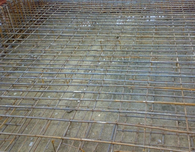
Three types of bars were used in reinforcement of a slab. These include straight bars, crank bar and an extra bar. The main steel is placed in which the straight steel is binded first, then the crank steel is placed and extra steel is placed in the end. The extra steel comes over the support while crank is encountered at distance of ¼(1-distance between the supports) from the surroundings supports.
For providing nominal cover to the steel in beam, cover blocks were used which were made of concrete and were casted with a thin steel wire in the center which projects outward. These keep the reinforcement at a distance from bottom of shuttering. For maintaining the gap between the main steel and the distribution steel, steel chairs are placed between them
SHUTTERING AND SCAFFOLDING
DEFINITION
The term ‘SHUTTERING’ or ‘FORMWORK’ includes all forms, moulds, sheeting, shuttering planks, walrus, poles, posts, standards, leizers, V-Heads, struts, and structure, ties, prights, walling steel rods, bolts, wedges, and all other temporary supports to the concrete during the process of sheeting.
FORM WORK
Forms or moulds or shutters are the receptacles in which concrete is placed, so that it will have the desired shape or outline when hardened. Once the concrete develops adequate strength, the forms are removed. Forms are generally made of the materials like timber, plywood, steel, etc.
Generally camber is provided in the formwork for horizontal members to counteract the effect of deflection caused due to the weight of reinforcement and concrete placed over that. A proper lubrication of shuttering plates is also done before the placement of reinforcement. The oil film sandwiched between concrete and formwork surface not only helps in easy removal of shuttering but also prevents loss of moisture from the concrete through absorption and evaporation.
The steel form work was designed and constructed to the shapes, lines and dimensions shown on the drawings. All forms were sufficiently water tight to prevent leakage of mortar. Forms were so constructed as to be removable in sections. One side of the column forms were left open and the open side filled in board by board successively as the concrete is placed and compacted except when vibrators are used. A key was made at the end of each casting in concrete columns of appropriate size to give proper bondings to columns and walls as per relevant IS.
CLEANING AND TREATMENT OF FORMS
All rubbish, particularly chippings, shavings and saw dust, was removed from the interior of the forms (steel) before the concrete is placed. The form work in contact with the concrete was cleaned and thoroughly wetted or treated with an approved composition to prevent adhesion between form work and concrete. Care was taken that such approved composition is kept out of contact with the reinforcement.
DESIGN
The form-work should be designed and constructed such that the concrete can be properly placed and thoroughly compacted to obtain the required shape, position, and levels subject
ERECTION OF FORMWORK
The following applies to all formwork:
a) Care should be taken that all formwork is set to plumb and true to line and level.
b) When reinforcement passes through the formwork care should be taken to ensure close
fitting joints against the steel bars so as to avoid loss of fines during the compaction of
concrete.
c) If formwork is held together by bolts or wires, these should be so fixed that no iron is
exposed on surface against which concrete is to be laid.
d) Provision is made in the shuttering for beams, columns and walls for a port hole of
convenient size so that all extraneous materials that may be collected could be
removed just prior to concreting.
e) Formwork is so arranged as to permit removal of forms without jarring the concrete.
Wedges, clamps, and bolts should be used where practicable instead of nails.
f) Surfaces of forms in contact with concrete are oiled with a mould oil of approved
quality. The use of oil, which darkens the surface of the concrete, is not allowed. Oiling
is done before reinforcement is placed and care taken that no oil comes in contact with
the reinforcement while it is placed in position. The formwork is kept thoroughly wet
during concreting and the whole time that it is left in place.
Immediately before concreting is commenced, the formwork is carefully examined to ensure the following:
a) Removal of all dirt, shavings, sawdust and other refuse by brushing and washing.
b) The tightness of joint between panels of sheathing and between these and any hardened core.
c) The correct location of tie bars bracing and spacers, and especially connections of
bracing.
d) That all wedges are secured and firm in position.
e) That provision is made for traffic on formwork not to bear directly on reinforcement
steel.
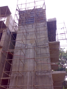
VERTICALITY OF THE STUCTURE
All the outer columns of the frame were checked for plumb by plumb-bob as the work proceeds to upper floors. Internal columns were checked by taking measurements from outer row of columns for their exact position. Jack were used to lift the supporting rods called props
STRIPPING TIME OR REMOVAL OF FORMWORK
Forms were not struck until the concrete has attained a strength at least twice the stress to which the concrete may be subjected at the time of removal of form work. The strength referred is that of concrete using the same cement and aggregates with the same proportions and cured under conditions of temperature and moisture similar to those existing on the work. Where so required, form work was left longer in normal circumstances
Form work was removed in such a manner as would not cause any shock or vibration that would damage the concrete. Before removal of props, concrete surface was exposed to ascertain that the concrete has sufficiently hardened. Where the shape of element is such that form work has re-entrant angles, the form work was removed as soon as possible after the concrete has set, to avoid shrinkage cracking occurring due to the restraint imposed. As a guideline, with temperature above 20 degree following time limits should be followed:
| Structural Component | Age |
| Footings | 1 day |
| Sides of beams, columns, lintels, wall | 2 days |
| Underside of beams spanning less than 6m | 14 days |
| Underside of beams spanning over 6m | 21 days |
| Underside of slabs spanning less than 4m | 7 days |
| Underside of slabs spanning more than 4m | 14 days |
| Flat slab bottom | 21 days |
Concreting
Concrete is a mixture of cement, sand, stone aggregates and water. A cage of steel rods used together with the concrete mix leads to the formation of Reinforced Cement Concrete popularly known as RCC.
Concrete has two main stages
1) Fresh Concrete
2) Hardened Concrete
Fresh Concrete should be stable and should not segregate or bleed during transportation and placing when it is subjected to forces during handling operations of limited nature. The mix should be cohesive and mobile enough to be placed in the form around the reinforcement and should be able to cast into the required shape without loosing continuity or homogeneity under the available techniques of placing the concrete at a particular job. The mix should be amenable to proper and through compaction into a dense, compact concrete with minimum voids under the existing facilities of compaction at the site. A best mix from the point of view of campactibility should achieve a 99 percent elimination of the original voids present.
Segregation
The stability of a concrete mix requires that it should not segregate and bleed during the transportation and placing. Segregation can be defined as separating out of the ingredients of a concrete mix, so that the mix is no longer in a homogeneous condition. Only the stable homogeneous mix can be fully compacted
The segregation depends upon the handling and placing operations. The tendency to segregate, amount of coarse aggregate, and with the increased slump. The tendency to segregate can be minimized by:
a. Reducing the height of drop by concrete.
b. Not using the vibration as a means of spreading a heap of of concrete into a level mass over a large area.
c. Reducing the continued vibration over a longer time, as the coarse aggregate tends to settle to the bottom and the scum would rise to the surface.
d. Adding small quantity of water which improves cohesion of the mix.
Bleeding
Bleeding is due to the rise of water in the mix to the surface because of the inability of the solid particles in the mix to hold all the mixing water during settling of particles under the effect of compaction. The bleeding causes formation of a porous, weak and non durable concrete layer at the top of placed concrete. In case of lean mixes bleeding may create capillary channels increasing the permeability of the concrete. When the concrete is placed in different layers and each layer is compacted after allowing certain time to lapse before the next layer is laid, the bleeding may cause a plane of weakness between two layers. Any laitance formed should be removed by brushing and washing before a new layer is added. Over compacting the surface should be avoided.
Hardened Concrete
One of the most important properties of the hardened concrete is its strength which represents the ability if concrete to resist forces. If the nature of the force is to produce compression, the strength is termed compressive strength. The compressive strength of hardened concrete is generally considered to be the most important property and is often taken as the index of the overall quality of concrete. The strength can indirectly give an idea of the most of the other properties of concrete which are related directly to the structure of hardened cement paste. A stronger concrete is dense, compact, impermeable and resistant to weathering and to some chemicals. However, a stronger concrete may exhibit higher drying shrinkage with consequent cracking, due to the presence of higher cement content.
Some of the other desirable properties like shear and tensile strengths, modulus of elasticity, bond, impact and durability etc. are generally related to compressive strength. As the compressive strength can be measured easily on standard sized cube or cylindrical specimens, it can be specified as a criterion for studying the effect of any variable on the quality of concrete. However, the concrete gives different values of any property under different testing conditions. Hence method of testing, size of specimen and the rate of loading etc. are stipulated while testing the concrete to minimize the variations in test results. The statistical methods are commonly used for specifying the quantitative value of any particular property of hardened concrete.
Compressive Strength
The compressive strength of concrete is defined as the load which causes the failure of specimen, per unit area of cross-section in uniaxial compression under given rate of loading. The strength of concrete is expressed as N/mm2. The compressive strength at 28 days after casting is taken as a criterion for specifying the quality of concrete. This is termed as grade of concrete. IS 456 – 2000 stipulates the use of 150 mm cubes.
Tensile Strength
The concrete has low tensile strength; it ranges from 8-12 per cent of its compressive strength. An average value of 10 per cent is generally adopted.
Shear Strength
The concrete subjected to bending and shear stress is accompanied by tensile and compressive stresses. The shear failures are due to resulting diagonal tension. The shear strength is generally 12-13 per cent of its compressive strength.
Bond Strength
The resistance of concrete to the slipping of reinforcing bars embedded in concrete is called bond strength. The bond strength is provided by adhesion of hardened cement paste, and by the friction of concrete and steel. It is also affected by shrinkage of concrete relative to steel. On an average bond strength is taken as 10 per cent of its compressive strength.
Facts about Cement and Concrete
1) Water required by 1 bag of cement is something in the range of 25-28 litres
2) Quality of concrete has nothing to do with its color.
3) The mortar / concrete should be consumed as early as possible after addition of water to it. The hydration of cement starts the moment water is added to it. As the hydration progresses the cement paste starts stiffening and loses its plasticity. The concrete should not be disturbed after this. Normally, this is about 45 – 50 minutes.
4) MPa is abbreviated form of mega Pascal, which is a unit of pressure. 1 MPa is equivalent to a pressure of 10Kg /cm2. The strength of concrete & cement is expressed in terms of pressure a standard cube can withstand. The Ordinary Portland Cement, commonly called OPC is available in three grades namely 33, 43 & 53 grades. Thus, for 43 grade cement standard cement & sand mortar cube would give a minimum strength of 43 MPa or 430 Kg /cm2 when tested under standard curing conditions for 28 days.
Compressive Strength of Concrete depends on following factors
(i) w/c ratio
(ii) Characteristics of cement
(iii) Characteristics of aggregates
(iv) Time of mixing
(v) Degree of compaction
(vi) Temperature and period of curing
(vii) Age of concrete
(viii)Air entertainment
(ix) Conditions of testing
Precautions for water to be used in concrete
* It is good to use potable quality of water.
It should be free from impurities and harmful ingredients.
Seawater isn’t recommended.
The water fit for mixing is fit for curing too
Use of minimum quantity of mixing water, consistent with the degree of workability required to enable easy placing and compaction of concrete, is advisable.
Ensure that water is measured and added.
Low water to cement ratio is essential for good performance of the structure in the long run.
Common Reasons for lack of quality in concrete work
Use of too much or too little water for mixing, or water carelessly added during mixing
Incomplete mixing of aggregate with cement
Improper grading of aggregates resulting in segregation or bleeding of concrete.
Inadequate compaction of concrete
Using concrete which has already begun to set.
Placing of concrete on a dry foundation without properly wetting it with water.
Use of dirty aggregate or water containing earthy matter, clay or lime.
Too much troweling of the concrete surface.
Leaving the finished concrete surface exposed to sun and wind during the first ten days after placing without protecting it and keeping it damp by proper methods of curing.
Construction joints are the joints provided between successive pours of concrete that have been carried out after a time lag. As far as possible the construction joints should be avoided and every care should be taken to keep their numbers minimal. Since, presence of these joints creates a plane of weakness within the concrete body, these joints should be preplanned and their location should be such that they are at places where they are subjected to minimum bending moment and minimum shear force.
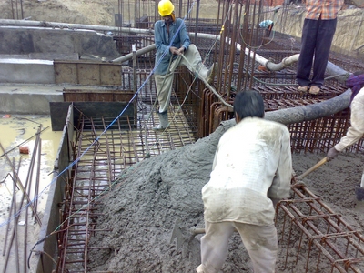
POURING AND CONSOLIDATION
Concrete (M20) was used for all works in column, beams and slabs. It was well consolidated by vibrating using portable mechanical vibrators. Care was taken to ensure that concrete is not over vibrated so as to cause segregation. The layers of concrete are so placed that the bottom layer does not finally set before the top layer is placed. The vibrators maintain the whole of concrete under treatment in an adequate state of agitation, such that deaeration and effective compaction is attained at a state commensurate with the supply of concrete from the mixers. The vibrator continue during the whole period occupied by placing of concrete, the vibrators being adjusted so that the centre vibrations approximate to the centre of the mass being compacted at the time of placing. Shaking of reinforcement for the purpose of compaction should be avoided. Compaction shall be completed before initial setting starts i.e. within thirty minute of addition of water to the dry mixture.
The concrete was deposited in its final position in a manner to preclude segregation of ingredients. In case of column and walls, the shuttering was so adjusted that the vertical drop of concrete is not more than 1.5 m at a time. In case of concreting of slabs and beams, the pipe from the batching plant was directly taken to the closest point.
COMPACTION
Green concrete has all the three phases – solids, water & air. In order to make the concrete impervious & attain its maximum strength it is required to remove the entrapped air from the concrete mass when it is still in plastic state. If the air is not removed completely, the concrete loses strength considerably. It has been observed that 5% voids reduce the strength by about 30% and 10% voids reduce the strength by over 50%. Compaction eliminates air bubbles and brings enough fine material both to the surface and against the forms to produce the desired finish. One can use such hand tools as steel rods, paddling sticks, or tampers, but mechanical vibrators are best. Any compacting device must reach the bottom of the form and be small enough to pass between reinforcing bars. Since the strength of the concrete member depends on proper reinforcement location, be careful not to displace the reinforcing steel.
C Compacting reinforced concrete work is very important and is done using iron rods. In case the thickness of concrete layers should be more than 15 cm. the most satisfactory method for compacting concrete properly is to consolidate each layer separately so that its top surface become level and fairy smooth before the next layer is placed. While tamping is carried out, care should be taken that the rod should penetrate the full layer of the last layer placed and to some extent into lying to ensure proper bond between bond between them. Secondly the reinforcement and formwork should not be disturbed from their positions.
Mechanical Compaction
M Mechanical compaction is done by the use of vibrators. Compaction of concrete by vibration is considered essential for all important works especially in situations where reinforcements are congested or the member is required is to have exposed to concrete surface finish. When vibraters are used leaner but stiff, concrete mix should be used to obtain greater durability and highest strength, mixes which are to stiff to consolidate by hand compaction can be easily compacted by mechanical compaction, in case the concrete is compacted by vibrations ,during which the vibrator communicates rapid vibrations to the particles, increases the fluidity of concrete. Due to vibrations the particles occupy a more stable position and concrete fills all the space and present is force out to the surface, resulting in dense and durable concrete.
Types of vibrators
Following are the type of vibrates usually used to compact concrete:
1. Internal vibrators
2. External vibrators
3. Surface vibrators
4. Vibrating table
Internal vibrator consists of metal road like vibrating head which is immersed in the full depth of concrete layer. It is also known as poker or needle vibrator and is consider to be most effective type of vibrator as it comes into intimate contact with concrete. External vibrators are placed against the concrete form-work and vibrating force for compaction is conveyed to the concrete through the form work. These vibrators are also called form vibrators. The vibrator is rigidly clamped to form work resting on a elastic spot, so that both the form and concrete are vibrated. Incase considerable proportion of work done is consumed in vibrating resulting in low efficiency of the system. Surface vibrators are mounted on platform and are generally used to compact and finish bridge, road slab etc. These are also external vibrators and are suitable for precast concrete work. It provides a reliable means of compaction of pre-cast concrete and has the adv of offering uniform vibration. Vibrating table is used for consolidation of pre-cast units. Surface vibrators is used there a wide horizontal surface occurs such as dams and very thick walls .large type of surface vibrators is there but pen type vibrator are used most. When concrete is placed on such tables, mechanical compaction takes place which has many advantages. Each vibrator have its own advantages and disadvantages, hence the choice between different types should be made correctly. Concrete to be compacted by vibration, should be designed properly. The consistency of concrete depends of conditions of placing, type of mix, and the efficiency of vibrator. The slum of such concrete should not be more than 5 cm in any case; otherwise segregation of concrete will take place, which should never be allowed to occur.
FINISH TO CONCRETE WORK:
a) All concrete while being poured against form work was worked with vibrator
rods & trowels as required so that good quality concrete is obtained.
b) All exposed surface of RCC lintels, beams, columns etc. were plastered to match
with adjoining plastered face of walls after suitably hacking the concrete surface.
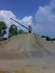
Concrete Mixers and Batching Plant
Concrete Plant, also known as a Batch Plant, is a device that combines various ingredients to form concrete. Some of these inputs include sand, water, aggregate (rocks, gravel, etc.), fly ash, potash, cement, and other ingredients to create concrete. There are two types of concrete plants, ready mix plants and central mix plant. A concrete plant can have a variety of parts and accessories, including but not limited to: mixers (either tilt-up or horizontal (or in some cases, both), cement batchers, aggregate batchers, conveyors, radial stackers, aggregate bins, cement bins, heaters, chillers, cement silos, batch plant controls, and dust collectors (to minimize environmental pollution).
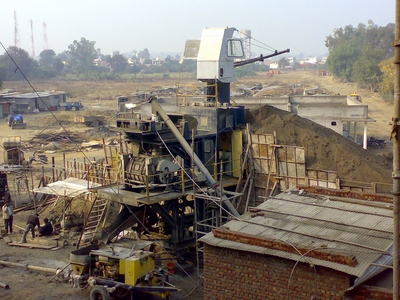
The front view of the plant from where it hauls coarse aggregate is shown below:-
Curing
The term ‘curing’ is used to include maintenance of a favorable environment for the continuation of chemical reactions, i.e. retention of moisture within, or supplying moisture to the concrete from an external source and protection against extremes of temperature
Following are the methods for curing different building parts:-
Walls - Water should be sprinkled from the top such that it covers the whole area of the wall and it should be remain wet.
Slab - Ponding should be done on the slab by constructing bunds of mortar
Beams and columns - The beams and columns can be maintained wet by tying gunny bags around the periphery and by maintaining it wet always.
Ponding, continuous sprinkling, covering with wet cloth, cotton mats or similar materials, covering with specially prepared paper, polyethylene, sealing coat applied as a liquid commonly known as ‘curing compound’ which hardens to form a thin protective membrane, are some of the methods by which concrete is cured. Curing should be started just after the surfaces begin to dry. Normally 7 to 14 days curing is considered adequate.
ADMIXTURE
Admixtures are those ingredients/materials that are added to cement, water, and aggregate mixture during mixing in order to modify or improve the properties of concrete for a required application.
Broadly the following five changes can be expected by adding an admixture
(i) Air entertainment
(ii) Water reduction for better quality
(iii) Acceleration of strength development
(iv) Improving the workability
(v) Water retention
Some of the important purposes for which the admixtures could be used are
1. Acceleration of the rate of strength development at early ages
2. Retardation of the initial setting of the concrete
3. Increase in strength
4. Improvement in workability
5. Reduction in heat of evolution
6. Increase in durability or in resistance to special conditions of exposure
7. Control of alkali-aggregate expansion
8. Reduction in the capillary flow of water and increase in impermeability to liquids
9. Improvement of pumpability and reduction in segregation in grout mixtures
10. Production of coloured concrete or mortar
The best way to test the admixture is by making trial mixes with the concrete materials to be used on the job and carefully observing and measuring the change in the properties. This way the compatibility of the admixture and the materials to be used, as well the effects of the admixture on the properties of fresh and hardened concrete can be observed. The amount of admixture recommended by the manufacturer or the optimum quantity determined by laboratory tests should be used
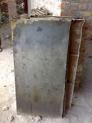
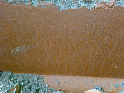
LEAKAGE AND WATER PROOFING
There are many reasons for leakage in concrete. Due to this leakage, the concrete not only looses its strength but also cause problem to the user. Normal concrete construction should not require water proofing materials, if it is designed and constructed properly with good quality and workmanship. But still to make it safe against the ill effects of water, liquid and powder form of water proofing material is used depending upon the availability of the material. Normally the usage per kg of cement is specified by the manufacturer for example: ACC’s waterproofing compound “ACCOPROOF” is available in powder form and 1 Kg packets. For normal purposes, 1 Kg is required to be used with 50 Kg (1 bag) of cement.
Leakages occur because of variety of reasons; some of which are mentioned below –
a) Accumulation of water, which start penetrating the surface.
b) Poor quality and improper proportioning of concrete constituents that make concrete permeable.
c) Poor compaction of concrete, which leave a lot of air voids.
d) Construction joints at two different works like concrete and brick works, and discontinuity in concrete casting (joint at old concrete and new concrete) leading minute cracks, which facilitate water movement.
e) Other structural cracks because of loading conditions and failure of the structure to withstand those stresses.
f) Movement of water from bottom to top because of capillary action.
Following figure shows the damp proofing material which was used at site:
Following measures may be useful to avoid leakages –
a) Provide good drainage facility with correct gradient at the places where there are chances for water to accumulate.
b) Use good quality of materials with correct proportioning in concrete. For example, use of blended cement and use of less water in concrete can reduce permeability of the structure. Similarly, proper proportioning of materials would help concrete becoming uniformly packed and dense.
c) Proper compaction of concrete with immersion vibrator to make it void less.
d) Avoid construction joints becoming a weaker point for water to travel. Some proactive and treatment measures would be useful.
e) Proper structural design and execution of members, which results no cracks for water to percolate.
f) Proper damp proofing course required to avoid movement of ground and other water from bottom to top. Some useful methods are like applying bitumen, concrete construction etc. at plinth level.
g) Use of water proofing compounds for water retaining structures.
DOORS AND WINDOWS
Wood absorbs moisture from air when the moisture content is high in the atmosphere and as a result it expands causing cracks in the wall. During dry atmosphere the wood contracts and a gap is formed between the wall and the frame of the door.
PLASTERING
Plaster protects structure from temperature variations; external attacks of sulphates, chlorides, etc. Plaster also provides smooth & aesthetic surface on RCC & Brickwork surface. The proportion of mortar used at site for ceiling coat is 1:4 and wall coat is 1:3. A plaster of 10 mm is done at ceiling and a plaster of 12.5mm is done at wall. Various precautions to be taken while the work of plastering is going on are:-
•Preferably use cements which releases low heat of hydration.
•Use optimum water at the time of mixing.
•Do not use dry cement on the plaster surface.
•At the junction of Brickwork & RCC, chicken mesh or fiber mesh may be used.
•Wet the surface before plastering and cure the surface for at least 10 to 12 days.
FLOORING
The purpose of a floor is to provide a horizontal sanitary surface to support the occupants of a building, furniture and equipment. A good floor should have strength and stability, resistance to dampness, good appearance, and freedom from maintenance etc.
Following are the common floor finishes –
Cement concrete flooring- It consists of 1:1.5:3 cement concrete laid to a thickness of 3” to 4”, over a strong sub base. Top surface is smoothened with cement punning. It has got good wearing properties and can be easily cleaned and maintained. If thickness is less, the size of stone aggregates is limited to ½”.
Tile flooring- It consists of ceramic, vitrified, terrazzo and cement tiles. Tiles give very pleasant appearance to floors. Also, it can be executed fast. Vitrified and Ceramic tiles have gained popularity over mosaic tiles because it doesn’t require grinding and polishing and the appearance is good and the tiles are quite strong.
In ground floor the cement concrete floor is to be on 7.5 cm base of lime concrete or weak cement concrete as per standard specifications. If the bases consist of cement concrete it shall be allowed to set for about 7 days. In case the base is of weak cement concrete the flooring shall commence within 48 hours of laying the base. In first floor or upper floor if c.c. floor is to be laid on R.C.C. slab, the surface shall be made rough with brushes while concrete is green. Before laying the c.c. floor the surface shall be cleaned, wetted and a neat cement wash shall be applied to get a good bond.A layer of brick brats ie broken bricks are laid before the laying of mortar and there by the tiles
ELECTRICAL CONDUITS
Separate conduits are laid for following systems:
a) Normal light, fan
b) Power points
c) AC points
d) Internet wiring
e) Fire alarm system
Concrete Mix Design As Per Indian Standard Code
Concrete Mix Design
Introduction
The process of selecting suitable ingredients of concrete and determining their relative amounts with the objective of producing a concrete of the required, strength, durability, and workability as economically as possible, is termed the concrete mix design. The proportioning of ingredient of concrete is governed by the required performance of concrete in 2 states, namely the plastic and the hardened states. If the plastic concrete is not workable, it cannot be properly placed and compacted. The property of workability, therefore, becomes of vital importance.
The compressive strength of hardened concrete which is generally considered to be an index of its other properties, depends upon many factors, e.g. quality and quantity of cement, water and aggregates; batching and mixing; placing, compaction and curing. The cost of concrete is made up of the cost of materials, plant and labour. The variations in the cost of materials arise from the fact that the cement is several times costly than the aggregate, thus the aim is to produce as lean a mix as possible. From technical point of view the rich mixes may lead to high shrinkage and cracking in the structural concrete, and to evolution of high heat of hydration in mass concrete which may cause cracking.
The actual cost of concrete is related to the cost of materials required for producing a minimum mean strength called characteristic strength that is specified by the designer of the structure. This depends on the quality control measures, but there is no doubt that the quality control adds to the cost of concrete. The extent of quality control is often an economic compromise, and depends on the size and type of job. The cost of labour depends on the workability of mix, e.g., a concrete mix of inadequate workability may result in a high cost of labour to obtain a degree of compaction with available equipment.
Requirements of concrete mix design
The requirements which form the basis of selection and proportioning of mix ingredients are :
a ) The minimum compressive strength required from structural consideration
b) The adequate workability necessary for full compaction with the compacting equipment available.
c) Maximum water-cement ratio and/or maximum cement content to give adequate durability for the particular site conditions
d) Maximum cement content to avoid shrinkage cracking due to temperature cycle in mass concrete.
Types of Mixes
1. Nominal Mixes
In the past the specifications for concrete prescribed the proportions of cement, fine and coarse aggregates. These mixes of fixed cement-aggregate ratio which ensures adequate strength are termed nominal mixes. These offer simplicity and under normal circumstances, have a margin of strength above that specified. However, due to the variability of mix ingredients the nominal concrete for a given workability varies widely in strength.
2. Standard mixes
The nominal mixes of fixed cement-aggregate ratio (by volume) vary widely in strength and may result in under- or over-rich mixes. For this reason, the minimum compressive strength has been included in many specifications. These mixes are termed standard mixes.
IS 456-2000 has designated the concrete mixes into a number of grades as M10, M15, M20, M25, M30, M35 and M40. In this designation the letter M refers to the mix and the number to the specified 28 day cube strength of mix in N/mm2. The mixes of grades M10, M15, M20 and M25 correspond approximately to the mix proportions (1:3:6), (1:2:4), (1:1.5:3) and (1:1:2) respectively.
3. Designed Mixes
In these mixes the performance of the concrete is specified by the designer but the mix proportions are determined by the producer of concrete, except that the minimum cement content can be laid down. This is most rational approach to the selection of mix proportions with specific materials in mind possessing more or less unique characteristics. The approach results in the production of concrete with the appropriate properties most economically. However, the designed mix does not serve as a guide since this does not guarantee the correct mix proportions for the prescribed performance.
For the concrete with undemanding performance nominal or standard mixes (prescribed in the codes by quantities of dry ingredients per cubic meter and by slump) may be used only for very small jobs, when the 28-day strength of concrete does not exceed 30 N/mm2. No control testing is necessary reliance being placed on the masses of the ingredients.
Factors affecting the choice of mix proportions
The various factors affecting the mix design are:
1. Compressive strength
It is one of the most important properties of concrete and influences many other describable properties of the hardened concrete. The mean compressive strength required at a specific age, usually 28 days, determines the nominal water-cement ratio of the mix. The other factor affecting the strength of concrete at a given age and cured at a prescribed temperature is the degree of compaction. According to Abraham’s law the strength of fully compacted concrete is inversely proportional to the water-cement ratio.
2. Workability
The degree of workability required depends on three factors. These are the size of the section to be concreted, the amount of reinforcement, and the method of compaction to be used. For the narrow and complicated section with numerous corners or inaccessible parts, the concrete must have a high workability so that full compaction can be achieved with a reasonable amount of effort. This also applies to the embedded steel sections. The desired workability depends on the compacting equipment available at the site.
3. Durability
The durability of concrete is its resistance to the aggressive environmental conditions. High strength concrete is generally more durable than low strength concrete. In the situations when the high strength is not necessary but the conditions of exposure are such that high durability is vital, the durability requirement will determine the water-cement ratio to be used.
4. Maximum nominal size of aggregate
In general, larger the maximum size of aggregate, smaller is the cement requirement for a particular water-cement ratio, because the workability of concrete increases with increase in maximum size of the aggregate. However, the compressive strength tends to increase with the decrease in size of aggregate.
IS 456:2000 and IS 1343:1980 recommend that the nominal size of the aggregate should be as large as possible.
5. Grading and type of aggregate
The grading of aggregate influences the mix proportions for a specified workability and water-cement ratio. Coarser the grading leaner will be mix which can be used. Very lean mix is not desirable since it does not contain enough finer material to make the concrete cohesive.
The type of aggregate influences strongly the aggregate-cement ratio for the desired workability and stipulated water cement ratio. An important feature of a satisfactory aggregate is the uniformity of the grading which can be achieved by mixing different size fractions.
6. Quality Control
The degree of control can be estimated statistically by the variations in test results. The variation in strength results from the variations in the properties of the mix ingredients and lack of control of accuracy in batching, mixing, placing, curing and testing. The lower the difference between the mean and minimum strengths of the mix lower will be the cement-content required. The factor controlling this difference is termed as quality control.
Mix Proportion designations
The common method of expressing the proportions of ingredients of a concrete mix is in the terms of parts or ratios of cement, fine and coarse aggregates. For e.g., a concrete mix of proportions 1:2:4 means that cement, fine and coarse aggregate are in the ratio 1:2:4 or the mix contains one part of cement, two parts of fine aggregate and four parts of coarse aggregate. The proportions are either by volume or by mass. The water-cement ratio is usually expressed in mass
Factors to be considered for mix design
ð The grade designation giving the characteristic strength requirement of concrete.
ð The type of cement influences the rate of development of compressive strength of concrete.
ð Maximum nominal size of aggregates to be used in concrete may be as large as possible within the limits prescribed by IS 456:2000.
ð The cement content is to be limited from shrinkage, cracking and creep.
ð The workability of concrete for satisfactory placing and compaction is related to the size and shape of section, quantity and spacing of reinforcement and technique used for transportation, placing and compaction.
Procedure
1. Determine the mean target strength ft from the specified characteristic compressive strength at 28-day fck and the level of quality control.
ft = fck + 1.65 S
where S is the standard deviation obtained from the Table of approximate contents given after the design mix.
2. Obtain the water cement ratio for the desired mean target using the emperical relationship between compressive strength and water cement ratio so chosen is checked against the limiting water cement ratio. The water cement ratio so chosen is checked against the limiting water cement ratio for the requirements of durability given in table and adopts the lower of the two values.
3. Estimate the amount of entrapped air for maximum nominal size of the aggregate from the table.
4. Select the water content, for the required workability and maximum size of aggregates (for aggregates in saturated surface dry condition) from table.
5. Determine the percentage of fine aggregate in total aggregate by absolute volume from table for the concrete using crushed coarse aggregate.
6. Adjust the values of water content and percentage of sand as provided in the table for any difference in workability, water cement ratio, grading of fine aggregate and for rounded aggregate the values are given in table.
7. Calculate the cement content form the water-cement ratio and the final water content as arrived after adjustment. Check the cement against the minimum cement content from the requirements of the durability, and greater of the two values is adopted.
8. From the quantities of water and cement per unit volume of concrete and the percentage of sand already determined in steps 6 and 7 above, calculate the content of coarse and fine aggregates per unit volume of concrete from the following relations:
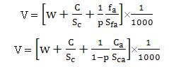
where V = absolute volume of concrete
= gross volume (1m3) minus the volume of entrapped air
Sc = specific gravity of cement
W = Mass of water per cubic metre of concrete, kg
C = mass of cement per cubic metre of concrete, kg
p = ratio of fine aggregate to total aggregate by absolute volume
fa, Ca = total masses of fine and coarse aggregates, per cubic metre of concrete, respectively, kg, and
Sfa, Sca = specific gravities of saturated surface dry fine and coarse aggregates, respectively
9. Determine the concrete mix proportions for the first trial mix.
10. Prepare the concrete using the calculated proportions and cast three cubes of 150 mm size and test them wet after 28-days moist curing and check for the strength.
11. Prepare trial mixes with suitable adjustments till the final mix proportions are arrived at.
Tests Conducted To Check Quality Of Concrete
Test conducted on site for quality control
Slump test
This is a site test to determine the workability of the ready mixed concrete just before its placing to final position inside the formwork, and is always conducted by the supervisor on site. However in mid of concreting process , should the site supervisor visually finds that the green concrete becomes dry or the placement of concrete has been interrupted , a re-test on the remaining concrete should be conducted in particular of the pour for congested reinforcement area . The procedure of test in brief is as follows: -
1. Ensure the standard Slump Cone and associated equipment are clean before test and free from hardened concrete.
2. Wet the Slump Cone and drain away the superfluous water.
3. Request the mixer or concrete truck to well mix the concrete for additional 5 minutes.
4. Place the Slump Cone on one side ( i.e. not in middle ) of the base plate on leveled ground and stand with feet on the foot-pieces of cone .
5. Using a scoop and fill the cone with sampled concrete in 3 equal layers, each of about 100mm thick.
6. Compact each layer of concrete in turn exactly 25 times with a Slump Rod, allowing the rod just passes into the underlying layer.
7. While tamping the top layer, top up the cone with a slight surcharge of concrete after the tamping operation.
8. Level the top by a “sawing and rolling” motion of the Slump Rod across the cone.
9. With feet are still firmly on the foot-pieces, wipe the cone and base plate clean and remove any leaked concrete from bottom edge of the Slump Cone.
10. Leave the foot-pieces and lift the cone carefully in a vertical up motion in a few seconds time.
11. Invert the cone on other side and next to the mound of concrete.
12. Lay the Slump Rod across the inverted cone such that it passes above the slumped concrete at its highest point.
13. Measure the distance between the underside of rod and the highest point of concrete to the nearest 5mm.
14. This reading is the amount that the sampled concrete has slumped.
15. If the concrete does not show an acceptable slump, repeat the test with another sample.
16. If the repeated test still does not show an acceptable slump, record this fact in the report, or reject that load of concrete.
Compression test
The Compression Test is a laboratory test to determine the characteristic strength of the concrete but the making of test cubes is sometimes carried out by the supervisor on site. This cube test result is very important to the acceptance of insitu concrete work since it demonstrates the strength of the design mix.
The procedure of making the test cubes is as follows: -
1. 150 mm standard cube mold is to be used for concrete mix and 100 mm standard cube mold is to be used for grout mix.
2. Arrange adequate numbers of required cube molds to site in respect with the sampling sequence for the proposed pour.
3. Make sure the apparatus and associated equipment ( see Fig 7 – 6 ) are clean before test and free from hardened concrete and superfluous water .
4. Assemble the cube mold correctly and ensure all nuts are tightened.
5. Apply a light coat of proprietary mold oil on the internal faces of the mold.
6. Place the mold on level firm ground and fill with sampled concrete to a layer of about 50 mm thick.
7. Compact the layer of concrete thoroughly by tamping the whole surface area with the Standard Tamping Bar. (Note that no less than 35 tamps / layer for 150 mm mold and no less than 25 tamps / layer for 100 mm mold).
8. Repeat Steps 5 & 6 until the mold is all filled. (Note that 3 layers to be proceeded for 150 mm mold and 2 layers for 100 mm mold).
9. Remove the surplus concrete after the mold is fully filled and trowel the top surface flush with the mold.
10. Mark the cube surface with an identification number (say simply 1, 2, 3, etc) with a nail or match stick and record these numbers in respect with the concrete truck and location of pour where the sampled concrete is obtained.
11. Cover the cube surface with a piece of damp cloth or polythene sheeting and keep the cube in a place free from vibration for about 24 hours to allow initial set .
12. Strip off the mold pieces in about 24 hours after the respective pour is cast. Press the concrete surface with the thumb to see any denting to ensure the concrete is sufficiently hardened, or otherwise de-molding has to be delayed for one more day and this occurrence should be stated clearly in the Test Report.
13. Mark the test cube a reference number with waterproof felt pen on the molded side, in respect with the previous identification number.
14. Place the cube and submerge in a clean water bath or preferably a thermostatically controlled curing tank until it is delivered to the accredited laboratory for testing.
Checking Quality of Fine Aggregates and Bricks
For checking the quality of fine aggregates, a field test was conducted in which the sand was placed in a flask containing water. The sand was allowed to settle for some time and then after few hours the reading of the silt or other impurity layer is takenIf that reading is less than 5% of the total sand that is put in the flask, then we accept the sand but if it is more than 5% the sand is rejected. Bricks were sent to the college laboratory for testing and thereby checking the quality of the bricks used at site.
Problems Faced At Site - Project Report - Multistoried Boys Hostel
Problems Faced At Site
There were numerous problems which were faced at site. Some of these were purely due to the human errors and poor workmanship but some were due to unseen factors.
- There was a problem in providing beams at one location as per the standard drawings so the drawings were changed by consulting the structural designers and architect
- There was problem pouring concrete in one beam due to small area available for pouring and compacting. The solution to this problem was that the size of steel was increased but the number of steel bars was decreased so as to provide the total area same.
- No window was there in staircases which lead to complete darkness, so it was decided to change the drawing by consulting the concerned authorities.
- The depth if beam above the door was 3’5” earlier but to keep the size of the door as per the standard it was changed to 3’.
- Frequent power cuts lead to increase in the cost of construction as generators were used to meet the power requirements
- Laying of foundations was postponed by 1 month due to the rainy season.
4 comments:
This is really good information thanks for post
Concrete Mix Design
Concrete Mix Design calculation
Great article—very clear and informative. I especially liked the way you explained the key points in a practical way. Thanks for sharing such useful insights! MILLING & DEAERATING SYSTEM
A well-structured Detailed Project Report Format is important for clear business planning. Taxlegit prepares reports covering objectives, financial projections, market analysis, and operational details. This helps entrepreneurs present their ideas professionally to banks or investors. Proper documentation reduces confusion and supports better decision-making at every stage of business setup and growth.
If your business requires strong financial governance and internal controls, Taxlegit offers expert assistance with SOX Compliance. It helps ensure transparency, risk management, and regulatory adherence in financial reporting. With proper compliance systems in place, businesses can build investor confidence and avoid legal risks. A valuable solution for companies aiming for robust financial control frameworks.
Post a Comment