
Hydroelectric Power Generation
The electrical power obtained from conversion of potential and kinetic energy of water is called Hydroelectric power
PE=WZ
where
PE= potential energy
W =total weight of the water
Z =vertical distance water can fall
Power is the rate at which energy is produced or utilized:
The electrical power obtained from conversion of potential and kinetic energy of water is called Hydroelectric power
PE=WZ
where
PE= potential energy
W =total weight of the water
Z =vertical distance water can fall
Power is the rate at which energy is produced or utilized:
1 horsepower (hp) =550 ft lb/s
1 kilowatt (kW) = 738 ft lb/s
1 hp= 0.746 kW
1 kW =1.341 hp
Power obtained from water flow may be computed from
hp=? Qwh/550= ?Qh/8.8
kW=? Qwh/738= ? Qh/11.8
where
kW= kilowatt
hp= horsepower
Q= flow rate, ft3/s (m3/s)
w =unit weight of water 62.4 lb/ft3 (998.4
kg/m3)
h = effective head total elevation difference minus line losses due to friction and turbu- lence, ft (m)
?= efficiency of turbine and generator
Venturimeter Flow Computations
Flow through a venturimeter is given by
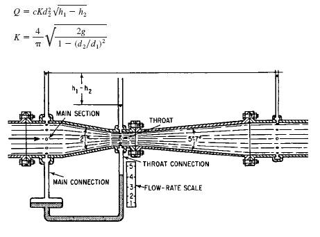
where
Q= flow rate, ft3/s (m3/s)
c =empirical discharge coefficient dependent on throat velocity and diameter
d1= diameter of main section, ft (m)
d2= diameter of throat, ft (m)
h1= pressure in main section, ft (m) of water
h2= pressure in throat section, ft (m) of water
Economical Sizing
ECONOMICAL SIZING OF DISTRIBUTION PIPING.
An equation for the most economical pipe diameter for a distribution system for water is
D=0.215*(fbQ3aS/aiHa)1/7
where
D= pipe diameter, ft (m)
f =Darcy–Weisbach friction factor
b =value of power, $/hp per year ($/kW per year)
Qa= average discharge, ft3/s (m3/s)
S =allowable unit stress in pipe, lb/in2 (MPa)
a= in-place cost of pipe, $/lb ($/kg)
i =yearly fixed charges for pipeline (expressed as a fraction of total capital cost)
Ha =average head on pipe, ft (m)
Flow From Wells
The steady flow rate Q can be found for a gravity well by using the Dupuit formula:
Q =[1.36K(H 2-h 2)]/log(D/d)
where
Q =flow, gal/day (liter/day)
K= hydraulic conductivity, ft/day (m/day), under
1:1 hydraulic gradient
H= total depth of water from bottom of well to free-water surface before pumping, ft (m)
h= H minus drawdown, ft (m)
D= diameter of circle of influence, ft (m)
d =diameter of well, ft (m)
The steady flow, gal/day (liter/day), from an artesian well is given by
Q=[2.73Kt(H -h)]/log(D/d)
where
t = thickness of confined aquifer, ft (m).
Water Flow For Firefighting
The demand rate of water for fighting fire is very high though the total quantity of water used for fighting fires is normally quite small. The fire demand as established by the American Insurance Association is
G=1020?P(1 -0.01?P)
where
G =fire demand rate in gal/min (liter/s)
P= population in thousands.
Groundwater
Groundwater is subsurface water in porous strata within a zone of saturation. Aquifers are groundwater formations capable of furnishing an economical water supply. Those formations from which extractions cannot be made economically are called aquicludes.
Permeability indicates the ease with which water moves through a soil and determines whether a groundwater formation is an aquifer or aquiclude.
The rate of movement of groundwater is given by
Darcy’s law:
Q=KIA
where
Q =flow rate, gal/day (m3/day)
K= hydraulic conductivity, ft/day (m/day)
I =hydraulic gradient, ft/ft (m/m)
A =cross-sectional area, perpendicular to direction of flow, ft2 (m2)
Method For Determining Runoff
METHOD FOR DETERMINING RUNOFF FOR MINOR HYDRAULIC STRUCTURES
The most common means for determining runoff for minor hydraulic structures is the rational formula:
Q=CIA
where
Q= peak discharge, ft3/s (m3/s)
C =runoff coefficient percentage of rain that appears as direct runoff
I= rainfall intensity, in/h (mm/h)
A= drainage area, acres (m2)
COMPUTING RAINFALL INTENSITY.
Chow lists 24 rainfall-intensity formulas of the form:
Read the rest of this entry »
Evaporation And Transpiration
The Meyer equation, developed from Dalton’s law, is one of many evaporation formulas and is popular for making evaporation-rate calculations:
E=C (ew-ea) ?
?=1+0.1w
where
E= evaporation rate, in 30-day month
C= empirical coefficient, equal to 15 for small, shallow pools and 11 for large, deep reservoirs
ew= saturation vapor pressure, in (mm), of mercury, corresponding to monthly mean air tempera- ture observed at nearby stations for small bodies of shallow water or corresponding to water temperature instead of air temperature for large bodies of deep water.
ea= actual vapor pressure, in (mm), of mercury, in air based on monthly mean air temperature and relative humidity at nearby stations for small bodies of shallow water or based on information obtained about 30 ft (9.14 m) above the water surface for large bodies of deep water.
w= monthly mean wind velocity, mi/h (km/h), at about 30 ft (9.14 m) aboveground
? =wind factor
Prediction Of Sediment Delivery Rate
Rate of sediment accumulation in a reservoir can be found by two methods.
One approach depends on historical records of the silting rate for existing reservoirs and is purely empirical. The second general method of calculating the sediment delivery rate involves determining the rate of sediment transport as a function of stream discharge and density of suspended silt.
The quantity of bed load is considered a constant func- tion of the discharge because the sediment supply for the bed-load forces is always available in all but lined channels. An accepted formula for the quantity of sediment trans- ported as bed load is the Schoklitsch formula:
Gb=86.7*S3/2 (Qi - bqo)/ ? Dg
Read the rest of this entry »
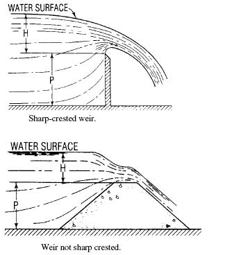
Weirs
Weir is defined as a barrier over which the water flows in an open channel. The edge or surface over which the water flows is called the crest. The overflowing sheet of water is the nappe.
If the nappe discharges into the air, the weir has free discharge. If the discharge is partly under water, the weir is submerged or drowned.
Types of Weirs.
A weir with a sharp upstream corner or edge such that the water springs clear of the crest is a sharp-crested weir.
All other weirs are classed as weirs not sharp crested. Sharp-crested weirs are classified according to the shape of the weir opening, such as rectangular weirs, triangular or V-notch weirs, trapezoidal weirs, and parabolic weirs. Weirs not sharp crested are classified according to the shape of their cross section, such as broad-crested weirs, triangular weirs, and trapezoidal weirs.
The channel leading up to a weir is the channel of approach. The mean velocity in this channel is the velocity of approach. The depth of water producing the discharge is the head.
Sharp-crested weirs are useful only as a means of meas- uring flowing water. In contrast, weirs not sharp crested are commonly incorporated into hydraulic structures as control or regulation devices, with measurement of flow as their secondary function.
Hydraulic Jump
The abrupt increase in depth of rapidly flowing water is called hydraulic depth.Flow at the jump changes from a supercritical to a subcritical stage with an accompanying loss of kinetic energy. The change in depth occurs over a finite distance, known as the length of jump. The upstream surface of the jump, known as the roller, is a turbulent mass of water.
The depth before a jump is the initial depth, and the depth after a jump is the sequent depth. The specific energy for the sequent depth is less than that for the initial depth because of the energy dissipation within the jump.
F=[ d22- d12]w/2
where d1 =depth before jump, ft (m)
d2 =depth after jump, ft (m)
w=unit weight of water, lb/ft3 (kg/m3)
Manning’s Equation For Open Channels
One of the more popular of the numerous equations developed for determination of flow in an open channel is Manning’s variation of the Chezy formula:
V=C ?RS
where
R= hydraulic radius, ft (m)
V =mean velocity of flow, ft/s (m/s)
S= slope of energy grade line or loss of head due to friction, ft/linear ft (m/m), of channel
C =Chezy roughness coefficient
Read the rest of this entry »
Critical Depth of Open-Channel Flow
For a given value of specific energy, the critical depth gives the greatest discharge, or conversely, for a given discharge, the specific energy is a minimum for the critical depth.
Open Channel Flow
The flow in the pipe is said to be open channel if the pipe is only half full eg Free surface flow, or open-channel flow, includes all cases of flow in which the liquid surface is open to the atmosphere.
Forces Due To Pipe Bends
The momentum change and the unbalanced internal pressure of the water leads to forces on the pipes
The force diagram in figure is a convenient method for finding the resultant force on a bend. The forces can be resolved into X and Y components to find the magnitude and direction of the resultant force on the pipe.
Read the rest of this entry »
Temperature Expansion Of Pipe
If a pipe is subject to a wide range of temperatures, the stress, lb/in2 (MPa), due to a temperature change is
Read the rest of this entry »
Pipe Stresses Perpendicular To The Longitudinal Axis
The internal or external pressures on the pipe walls cause the stresses acting perpendicular to the longitudinal axis of a pipe.
Internal pressure creates a stress commonly called hoop tension
The sum of the forces in the horizontal direction is
pD=2F
where
p= internal pressure, lb/in2 (MPa)
D= outside diameter of pipe, in (mm)
F= force acting on each cut of edge of pipe, lb (N)
Hence, the stress, lb/in2 (MPa) on the pipe material is
pD=F/A= pD/2t
where
A= area of cut edge of pipe, ft2 (m2)
t= thickness of pipe wall, in (mm).
Water Hammer
Water hammer is a change in pressure, either above or below the normal pressure, caused by a variation of the flow rate in a pipe.
Orifice Discharge Into Diverging Conical Tubes
This type of tube can greatly increase the flow through an orifice by reducing the pressure at the orifice below atmospheric. The formula that follows for the pressure at the entrance to the tube is obtained by writing the Bernoulli equation for points 1 and 3 and points 1 and 2
Fluid Jets
Where the effect of air resistance is small, the path of projectile is followed when a fluid discharged through an orifice into the air
The initial velocity of the jet is
V0 = Cv?2gh
where h= head on center line of orifice, ft (m),
Cv =coefficient of velocity.
The direction of the initial velocity depends on the orientation of the surface in which the orifice is located.The velocity of the jet in the X direction (horizontal) remains constant
Vx = V0 = Cv ?2gh
The velocity in the Y direction is initially zero and there after a function of time and the acceleration of gravity:
Vy = gt
The X coordinate at time t is
X = Vx t = tCv ?2gh
The Y coordinate is
Y = Vavg t= gt2/2
where Vavg =average velocity over period of time t.
The equation for the path of the jet:
X2 = Cv* Cv *4hY
Discharge under Falling Head.
When the inflow is less than the outflow then that condition is called the falling head condition.The time required for a certain quantity of water to flow from a reservoir can be calculated by equating the volume of water that flows through the orifice or pipe in time dt to the volume decrease in the reservoir. If the area of the reservoir is constant,
t=2A (?h1 -?h2)/ (Ca ?2g)
where h1= head at the start, ft (m)
h2 =head at the end, ft (m)
t =time interval for head to fall from h1 to h2,(s )
Flow Through Orifices.
Orifice Discharge into Free Air
An orifice is an opening with a closed perimeter through which water flows. Orifices may have any shape, although they are usually round, square, or rectangular.
Read the rest of this entry »
Pressure(head)Changes Caused By Pipe Size Change.
Energy losses occur in pipe contractions, bends, enlargements, and valves and other pipe fittings. These losses can usually be neglected if the length of the pipeline is greater than 1500 times the pipe diameter. However, in short pipe- lines, because these losses may exceed the friction losses, minor losses must be considered.
Read the rest of this entry »
Commonly Used Formula in Hydraulics
Darcy Weisbach formula
Darcy Weisbach formula which is valid for laminar or turbulent flow in all fluids is one of the most commonly used formula for determining the head loss.
hf=[fLV2]/2gD
where
hf=head loss due to friction, ft (m)
f= friction factor
L =length of pipe, ft (m)
D= diameter of pipe, ft (m)
V =velocity of fluid, ft/s (m/s)
g =acceleration due to gravity, 32.2 ft/s2 (9.81 m/s2)
Fluid flow in pipes
Laminar Flow
Its is a flow in which the fluid particles move in parallel layers in a single direction.Due to the parabolic velocity distribution in laminar flow, a shearing stress is developed. As this shearing stress increases, the viscous forces become unable to damp out disturbances, and turbulent flow results. The region of change is dependent on the fluid velocity, density, and viscosity and the size of the conduit.
Similitude for physical models
A physical model is a system whose operation can be used to predict the characteristics of a similar system, or prototype, usually more complex or built to a much larger scale.”A model can be either smaller or bigger than the real construction.It is believed that model is always smaller but that is not true always for example if we want to make a very small computer chip then to illustrate its function properly the model is made bigger as compared to the original chip.
Bernoulli Equation
For fluid energy, the law of conservation of energy is represented by the Bernoulli equation(for ideal fluid only):
Z1+p1/w+V12/2g=Z2+p2/w+V22/2g
Viscosity
Viscosity of a fluid, also called the coefficient of viscosity, absolute viscosity, or dynamic viscosity, is a measure of its resistance to flow. It is expressed as the ratio of the tangential shearing stresses between flow layers to the rate of change of velocity with depth
Facts About Viscosity are:-
1)Viscosity decreases as temperature increases.
2)The pressure effect is neglected in various engineering applications.
Water at 70°F (21.1°C) has a viscosity of 0.00002050 lb s/ft2 (0.00098 N s/m2).
3)Viscosity divided by density is called kinematic viscosity.
4)In hydraulics, viscosity is most frequently encountered in the calculation of Reynolds number to determine whether laminar, transitional, or completely turbulent flow exists.
No comments:
Post a Comment